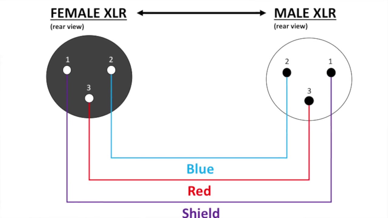
Xlr Wiring Pattern - Measure and cut the proper length of cable. Pin 1, pin 2, and pin 3. Web understanding the wiring diagram for balanced xlr connections is essential for setting up audio systems properly and ensuring optimal sound quality. Pin 2 carries the positive or “hot” audio signal, while pin 3 carries the negative or “cold” audio signal. Failure to do so may result in damage to your equipment. Please refer to documentation for specific pinouts. A small capacitor wired between xlr pin‑1 and the shell maintains. First, measure the length of cable that you need and cut your cable down to the proper size. The aes specifications do say that you should wire each pin‑1 to the shell, and there’s good sense behind that policy, but only if all of the equipment being connected together is built and wired correctly too. Web the wiring diagram for an xlr cable typically consists of three pins:
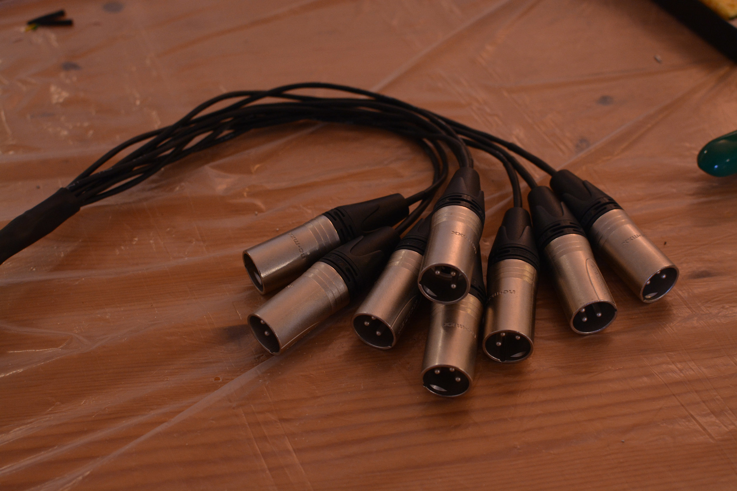
How to Build Your Own XLR Cables A Step by Step Guide Studio DIY
In a balanced xlr connection, there are three wires: Web understanding the wiring diagram for balanced xlr connections is essential for setting up audio systems.
Male Xlr Wiring Diagram
Clark wire and cable does. Most cable is sold by the foot, so if you’re making multiple cables you will need to cut them down.

Updated Drawing An XLR Wiring Diagram YouTube
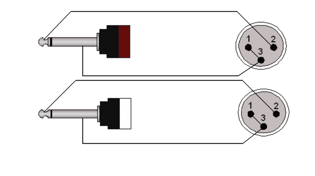
Web following are standard pinouts for audio (specifically xlr type connectors). Clark wire and cable does. Pin 2 carries the positive or “hot” audio signal,.

Female Xlr Wiring Diagram Organicent
Pin 1 is usually connected to the shield or ground wire of the cable, which helps reduce interference. Pin 1 (ground), pin 2 (positive/hot), and.
Stereo Xlr Wiring
Updated on apr 27, 2007 at 12:00 am. Remember to allow a couple of inches for each connector. Manufacturers may not follow standards listed below..
Standard Xlr Wiring Diagram Yamaha
Measure and cut the proper length of cable. Pin 1 (ground), pin 2 (positive/hot), and pin 3 (negative/cold). Failure to do so may result in.

xlr wiring guide
Pin 2 and pin 3 carry the balanced audio signal, which helps eliminate the. Web the wiring diagram for an xlr cable typically consists of.
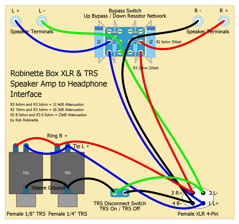
4 Pin Xlr Wiring Diagram Power Xlr Wiring Diagram Lable Mini Xlr 4 Pin
Manufacturers may not follow standards listed below. Pin 2 carries the positive or “hot” audio signal, while pin 3 carries the negative or “cold” audio.

⭐Wiring Diagram Xlr⭐ Mixedrace couples
A small capacitor wired between xlr pin‑1 and the shell maintains. Web understanding the wiring diagram for balanced xlr connections is essential for setting up.

XLR Pinout, Wiring Diagram Male and Female Connector ETechnoG
A small capacitor wired between xlr pin‑1 and the shell maintains. The aes specifications do say that you should wire each pin‑1 to the shell,.
Web Understanding The Wiring Diagram For Balanced Xlr Connections Is Essential For Setting Up Audio Systems Properly And Ensuring Optimal Sound Quality.
Pin 2 and pin 3 carry the balanced audio signal, which helps eliminate the. Web following are standard pinouts for audio (specifically xlr type connectors). In a balanced xlr connection, there are three wires: Pin 2 carries the positive or “hot” audio signal, while pin 3 carries the negative or “cold” audio signal.
The Aes Specifications Do Say That You Should Wire Each Pin‑1 To The Shell, And There’s Good Sense Behind That Policy, But Only If All Of The Equipment Being Connected Together Is Built And Wired Correctly Too.
Web the wiring diagram for an xlr cable typically consists of three pins: Failure to do so may result in damage to your equipment. Updated on apr 27, 2007 at 12:00 am. Measure and cut the proper length of cable.
Pin 1 (Ground), Pin 2 (Positive/Hot), And Pin 3 (Negative/Cold).
Pin 1 is usually connected to the shield or ground wire of the cable, which helps reduce interference. Most cable is sold by the foot, so if you’re making multiple cables you will need to cut them down to the proper length yourself. An xlr is wired for a balanced signal so that: First, measure the length of cable that you need and cut your cable down to the proper size.
Manufacturers May Not Follow Standards Listed Below.
Please refer to documentation for specific pinouts. Pin 1, pin 2, and pin 3. Remember to allow a couple of inches for each connector. Sos technical editor hugh robjohns replies :