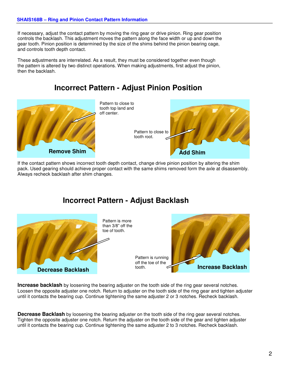
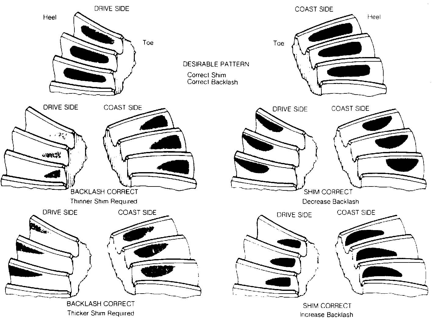
Ring And Pinion Tooth Contact Pattern - Ensuring peak performance and longevity. Increase backlash by loosening the bearing adjuster on the tooth side of the ring gear several notches. The toe of the gear is the portion of the tooth surface at the end towards the center. Web improper gear spacing will lead to wear and damage to your gear set. You don’t need to go much, maybe 0.005” to start with, set backlash run a pattern, repeat as necessary. Use shims to move the ring gear farther from the pinion gear to increase backlash. 3/8” off the toe end. Web paint ring gear with marking compound and roll the gear to. Rotate the pinion to turn the ring gear four complete revolutions on the drive side and then four in the opposite direction for the coast side. Obtain a contact pattern as shown in the photograph.

Once backlash is within spec you can set the pinion depth by reading
Use shims to move the ring gear closer to the pinion gear to decrease backlash. Incorrect backlash can lead to damaged gear. Web apply tooth.
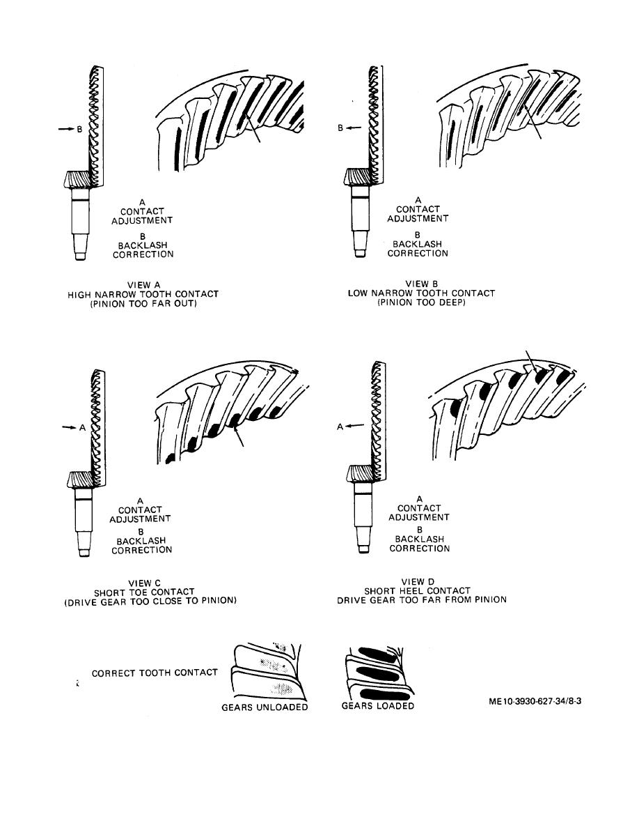
Figure 83. Proper piniontodifferential ring gear tooth contact pattern.
Use shims to move the ring gear farther from the pinion gear to increase backlash. The top land of a gear tooth is the surface.
Ring Gear Contact Pattern
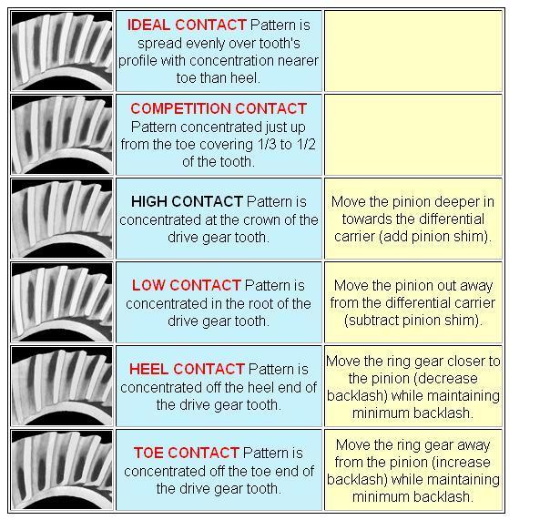
Web drive pattern moves deeper on the tooth (flank contact) and slightly toward the toe. High contact pattern is concentrated at the crown of the.
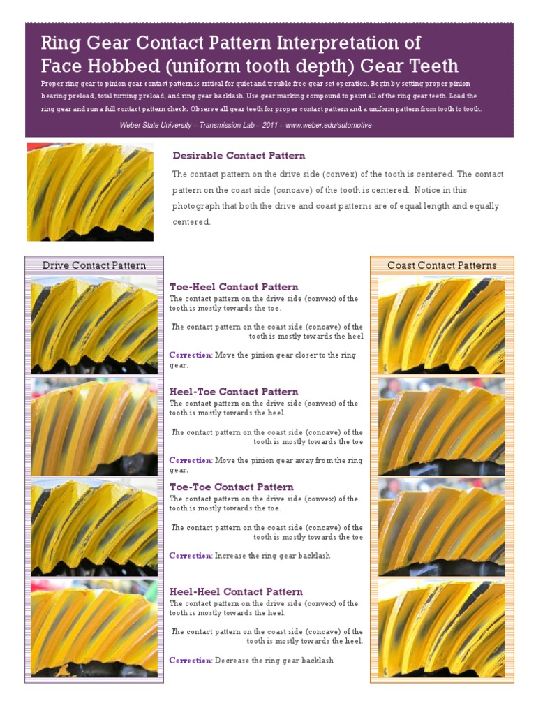
Weber_Ring_Gear_Contact_Pattern_Interpretation.pdf Gear Tooth
Use shims to move the ring gear farther from the pinion gear to increase backlash. Web ring and pinion gear pattern is one of the.
RING AND PINION TOOTH CONTACT PATTERN...mine with pic MGB & GT Forum
If the pattern is heavy on the “heel” (outboard area of the ring gear teeth), add shims. A decrease will move the. Ensuring peak performance.
Ring Gear Contact Pattern
In this video we give a quick d. Yukon provides highest quality drivetrain parts including differentials, axles, driveshafts, super joints and ring and pinion installation.
Ring Gear Contact Pattern
If the pattern is heavy on the “heel” (outboard area of the ring gear teeth), add shims. You don’t need to go much, maybe 0.005”.
How to Set up Your Rear Gear Correctly RacingJunk News
Web the final pinion position will be verified by using the gear contact pattern method described as follows: Carefully note the contact pattern that shows.

Differential Unitec automotive engineering study 2012
Resetting the pinion depth may be necessary. The toe of the gear is the portion of the tooth surface at the end towards the center..
The Easiest Way to Read Ring & Pinion Contact Patterns YouTube
2429 mercantile drive suite a rancho cordova, ca 95742. Web the final pinion position will be verified by using the gear contact pattern method, as.
The Top Land Of A Gear Tooth Is The Surface Of The Top Of The Tooth.
Pattern should range from just clear of the toe end to about. Web the final pinion position will be verified by using the gear contact pattern method described as follows: Sent from my iphone using h.a.m.b. Competition contact pattern concentrated just up from the toe covering 1/3 to 1/2 of the tooth.
Move The Pinion Gear Closer To The Ring Gear.
Rotate the pinion to turn the ring gear four complete revolutions on the drive side and then four in the opposite direction for the coast side. Web one of the most common questions we're asked is how to properly read contact pattern markings during differential gear setup. Coast pattern moves deeper on the tooth and toward the heel. Obtain a contact pattern as shown in the photograph.
Web Apply Tooth Contact Compound To The Ring Gear In Two Places.
Tooth contact pattern shown on the drive side of the gear teeth. 3/8” off the toe end. Use shims to move the pinion closer to the ring gear to move the drive pattern deeper on the tooth (flank contact) and slightly toward the toe. In this video we give a quick d.
You Don’t Need To Go Much, Maybe 0.005” To Start With, Set Backlash Run A Pattern, Repeat As Necessary.
Use shims to move the ring gear farther from the pinion gear to increase backlash. If your gear tooth pattern is too low, down towards the gear flank (root), you will need to decrease your pinion. Return to adjuster on the tooth side of the ring gear and tighten adjuster until it contacts the bearing cup. Web the final pinion position will be verified by using the gear contact pattern method, as described in this bulletin.