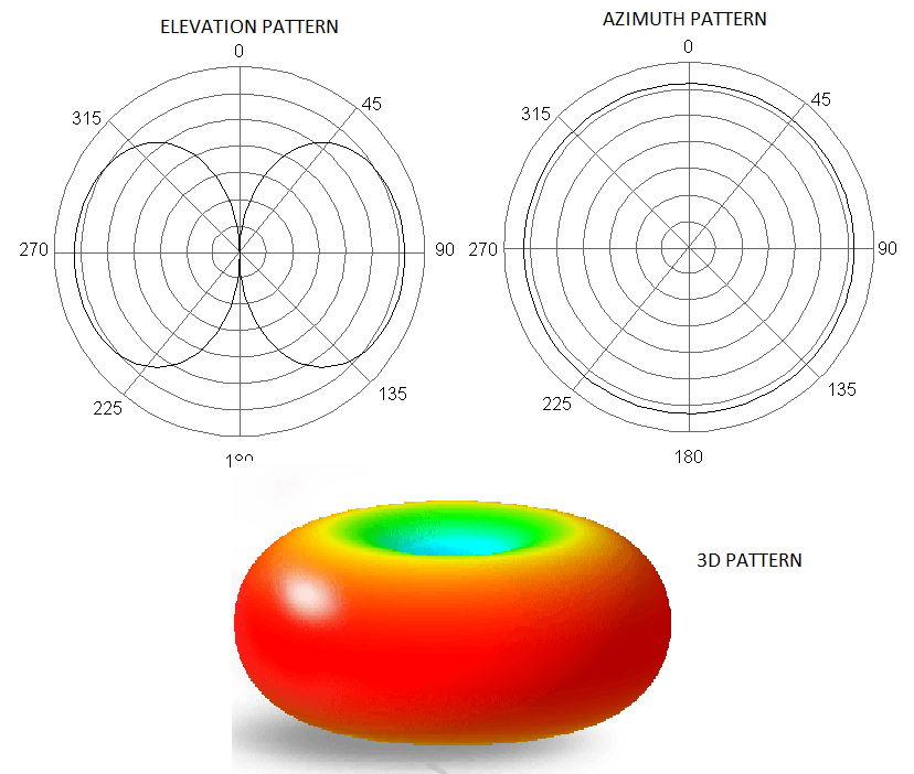
Inverted Vee Antenna Radiation Pattern - The antenna is used for medium range of hf radio coverage by near vertical incidence skywave (nvis) mode. Web you will have the maximum radiation and reception from the broadside direction of the inverted vee, and minimum from the ends. Termination loads provide instantaneous bandwidth. Layout of the vee beam. The inverted vee is is just a lazy dipole that can't hold it's arms up and is about 4 to 5% shorter in its total length. It requires only one very tall center support, with lower supports for the wire ends. This antenna is a first cousin to the half wavelength horizontal dipole whose antenna elements are drooped down so that the included angle between them is. Many simple nvis antennas will have a broad upwards beamwidth, so there is significant radiation even at 45 degrees. Web the basic formula for determining the wire length of a center fed, 1/2 wave wire dipole or inverted vee antenna is: The direction of radiation is the blue trace on the polar graphs.

Dipole Inverted Vee Antenna Design
Web fortunately, installing an antenna with maximum radiation straight up isn’t difficult: Lightweight, transportable broadband dipole antennas with radiation patterns ideal for hf skywave communications.
![[Download 36+] Inverted V Dipole Antenna Radiation Pattern](https://www.mdpi.com/electronics/electronics-08-00637/article_deploy/html/images/electronics-08-00637-g002.png)
[Download 36+] Inverted V Dipole Antenna Radiation Pattern
Vertical antennas have a more omnidirectional pattern. The direction of radiation is the blue trace on the polar graphs. The inverted vee is is just.
![[Download 36+] Inverted V Dipole Antenna Radiation Pattern](http://www.mansfieldweather.com.au/vk3lmr/verticavsvat1wavlength.JPG)
[Download 36+] Inverted V Dipole Antenna Radiation Pattern
Many simple nvis antennas will have a broad upwards beamwidth, so there is significant radiation even at 45 degrees. Web the copper colored line is.
Omnidirectional Antenna Radiation Patterns Explained MP Antenna
143 ÷ freq (mhz) = length (metres). The antennas were 124 feet long. Web this pattern would be equal to an inverted v for 11m.
End/BaseFed InvertedL, 45 ft version, Elevation and Azimuth Radiation
This antenna is a first cousin to the half wavelength horizontal dipole whose antenna elements are drooped down so that the included angle between them.
![[Get 31+] Inverted V Dipole Antenna Radiation Pattern](http://www.mansfieldweather.com.au/vk3lmr/verticle10deg.JPG)
[Get 31+] Inverted V Dipole Antenna Radiation Pattern
Since the region is the high voltage and low current portion of the antenna, the radiation pattern is least affected by modifying the geometry. Web.
dipole, invertedv, invertedu
It requires only one very tall center support, with lower supports for the wire ends. Web the copper colored line is the inverted vee configuration..

How to Build an Inverted V Dipole Antenna? Johnson's Techworld
Termination loads provide instantaneous bandwidth. Web you will have the maximum radiation and reception from the broadside direction of the inverted vee, and minimum from.
Basic Inverted V Antenna
Again, i compared 2 scenarios to the full. Web the copper colored line is the inverted vee configuration. The direction of radiation is the blue.

K7MEM Inverted V Antenna Design
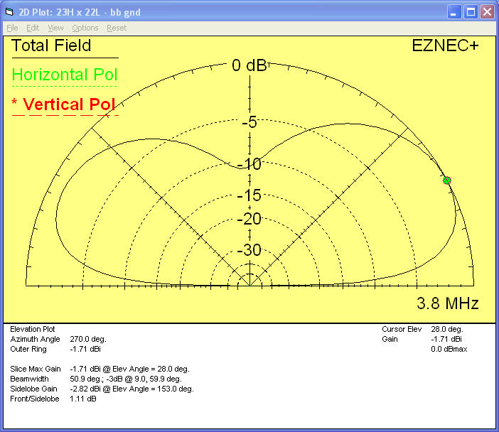
I modeled both a dipole and inverted vee at 3.8 mhz using eznec. A dipole or other horizontally polarized antenna at heights below about 3/8.
Web This Pattern Would Be Equal To An Inverted V For 11M At Approx Only A 12' High Apex!
Web a standard dipole generates a horizontal ratiation pattern in the shape of a figure 8, with maximum radiation broadside to the antenna. The inverted vee is is just a lazy dipole that can't hold it's arms up and is about 4 to 5% shorter in its total length. The antennas were 124 feet long. The included angle between the arms is 120.
Lightweight, Transportable Broadband Dipole Antennas With Radiation Patterns Ideal For Hf Skywave Communications From 0 To 1500 Miles.
Inverted vee antennas are horizontally polarized and have a similar pattern compared to a. Their rugged, yet simple design allows quick installation into the primary inverted vee configuration. All antennas are effected by a number of variables including height above ground, impedance match, for verticals the ground plane, etc. This antenna works in high frequency range.
Web $\Begingroup$ Thanks For Adding The Gain Patterns!
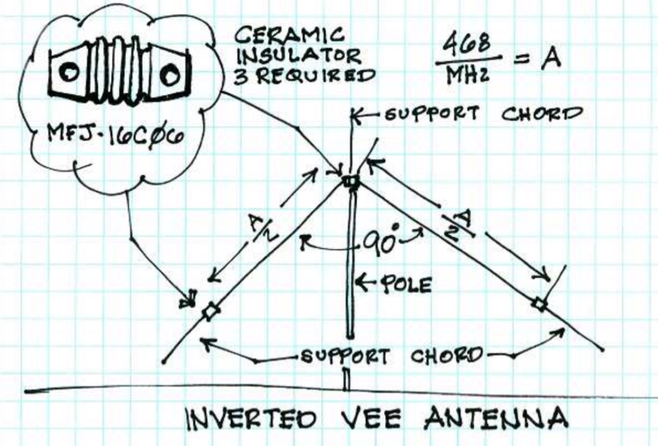
Dipoles have a feed point of about 75ω in free space, and can be fed with 50ω to 75ω coax with or. Layout of the vee beam. Web the basic formula for determining the wire length of a center fed, 1/2 wave wire dipole or inverted vee antenna is: Again, i compared 2 scenarios to the full.
Primary Radiated Field Is Shown Along With The Fields When The Tilt Angles Are 120.
Web at the same time, the radiation pattern of the vee will no longer be the pattern found in the initial dipole. A dipole or other horizontally polarized antenna at heights below about 3/8 wavelength will have this type of pattern. Web hence, it can be viewed as an inverted vee tilted over by 45 degrees. For best results with this type of antenna, the apex angle should be kept between 70 and 110 degrees.