Hole Pattern As Datum - To establish a datum axis on a feature such as a hole, there are a number of ways to place the datum symbol: That's been hashed over in this forum before. Web in a recent live instruction webinar, we answered four common gd&t questions that we have received from our students. Web hole pattern located by composite tolerancing (primary datum only in lower segment). This is an unusual situation, but it is possible. For this, i've simply declared the first set as a datum feature, and created a compound true position fcf for the other set using the first set as the secondary datum. Web the datum scheme simply does not reflect how the part functions. Web the 4 hole pattern: You can assign datums to hole patterns, concentric holes with gaps between them, width patterns, and concentric bosses. You can assign datums to hole patterns, concentric holes with gaps between them, width patterns, and concentric bosses.
Dimensioning Hole Patterns
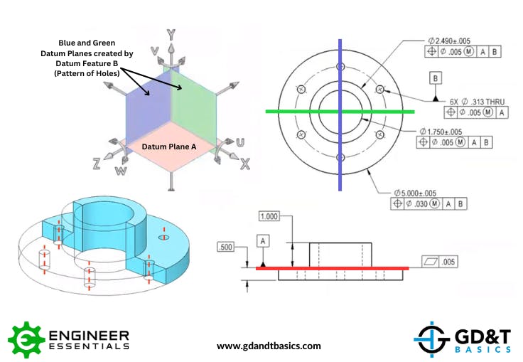
The better datum scheme, the one that reflects how the part functions and how it should be gaged, is shown below. Web your first plane.
Hole Pattern Position With Central Hole as Datum Drafting Standards
This is an unusual situation, but it is possible. The algorithms implemented in the software evaluate the measured features according to specifications of asme y14.5..
Common GD&T Student Questions A Pattern of Holes as a Datum Feature
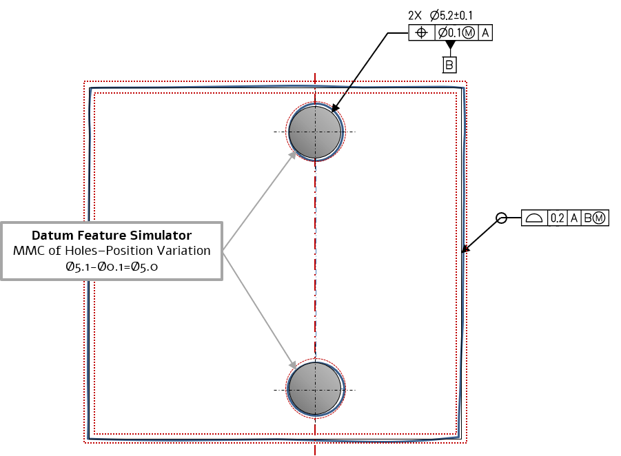
The algorithms implemented in the software evaluate the measured features according to specifications of asme y14.5. Note that the yellow and blue circles represent the.
Common GD&T Student Questions A Pattern of Holes as a Datum Feature
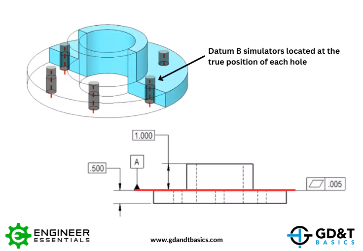
Create an axis through one of the holes (never use an axis that's part of a feature unless you want to make things more difficult).

Are You Using GD&T Correctly? Geometric Learning Systems
Web hole pattern located by composite tolerancing (primary datum only in lower segment). For this, i've simply declared the first set as a datum feature,.

Common GD&T Student Questions A Pattern of Holes as a Datum Feature
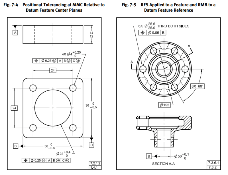
If a pattern of features (two or more) are being positioned with one feature control frame, then a single datum plane is allowed (because there.
Tolerance Of Position Dimensional Consulting
Secondary datum feature b the large hole. This is an unusual situation, but it is possible. It is a cover that gets bolted down to.

GD&T Tip Datums Watch placement of datum triangles in the latest
You can assign datums to hole patterns, concentric holes with gaps between them, width patterns, and concentric bosses. Two concentric hole pattern used as secondary.
Hole Pattern as a Datum Feature TEStechnologies
Basically, say we have 4 holes that are the same size. The algorithms implemented in the software evaluate the measured features according to specifications of.
Hole Pattern as a Datum Feature TEStechnologies
Take a look at the attached picture. After rethinking, individually won't be needed, as the datum feature symbol will have a direct leader to a.
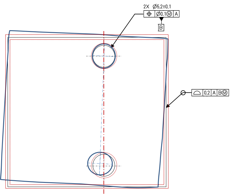
This Figure Represents One Of The Possible Displacements Of The Pattern.
Web the datum scheme simply does not reflect how the part functions. Create an axis through one of the holes (never use an axis that's part of a feature unless you want to make things more difficult) and then choose in dimension or whatever is right for the version of ptc software you are using. The hood is designed to mate with both pins. Take a look at the attached picture.
You Can Create Datums As Individual Features Or Patterns Using Counterbores And Countersinks.
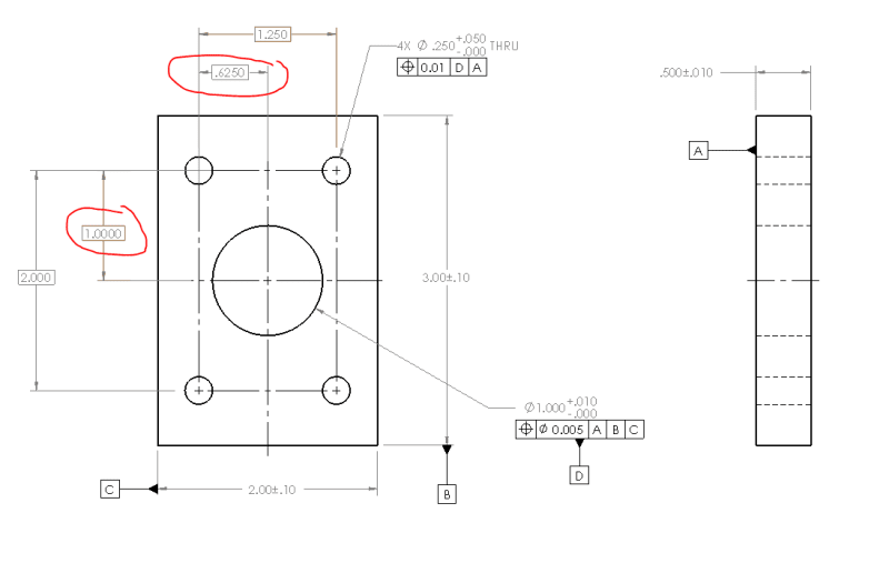
It is a cover that gets bolted down to the rest of the assembly by the four holes in the pattern. From either end of the bush and average it or insert a shaft thru the hole take dimension on the shaft near the assembly datum and arrive. The algorithms implemented in the software evaluate the measured features according to specifications of asme y14.5. The large hole in the middle of the part is then located relative to the pattern of four holes.
Web Hole Pattern As A Datum Feature.
Web this situation comes up a lot in our parts. The drawing below (figure 2), depicts design intent. The holes in the pattern have a feature size tolerance of ±0.1 mm and a position tolerance of 0.5 mm at mmc with respect to datum reference frame abc. To inspect this part, we need to create the datum reference frame.
Web A Datum Reference Symbol Is Typically Attached To The Diameter Dimension Of The Holes In A Pattern.
The position of these holes is defined using basic dimensions with respect to the datum reference frame abc. Note that the yellow and blue circles represent the tolerance zones with 0.5 mm and 0.1 mm diameters, respectively. To establish a datum axis on a feature such as a hole, there are a number of ways to place the datum symbol: In figure 3, we observe a composite tolerance created using buildit metrology software.