Gdt Pattern Of Holes - Web quickly shows how to use gd&t to locate a simple clearance hole on a flat plate.instagram: A simple example would be a set of holes (pattern) used to affix a name plate. It's really another virtual condition, but when it's applied to a datum feature of size all of the cool gd&t geeks call it a max material boundary. Web the datum scheme simply does not reflect how the part functions. Make sure to select ‘bilateral’ or ‘limit’ as tolerance type for features where the plus and minus limit are unequal. As we saw earlier, slots allow us to avoid overconstraint while having greater precision. (click on the image to enlarge.) image courtesy of. This can be polar (radius/angle) or cartesian (x,y coordinates) or. The true position is the exact coordinate, or location defined by basic dimensions or other means that represents the nominal value. This designator is commonly used for holes, radii, chamfers, surfaces, and any other types of repetitive.
True Position GD&T Basics
Let’s have a look at this simple plate with six holes in figure 1 and see how they are dimensioned. An example of this can.
Composite tolerancing a multifeature hole pattern Drafting Standards
An example of this can be seen in figure 3. In this drawing, the dimensions for the bolt circle diameter and the bolt hole pattern.

Common GD&T Student Questions A Pattern of Holes as a Datum Feature
That gives us the following true position formula: Web a datum reference symbol is typically attached to the diameter dimension of the holes in a.

GD&T Tip Datums Watch placement of datum triangles in the latest
True position = 2 x. Web using one of the holes as a datum, has the advantage that it translates more directly into an inspection.
Hole Pattern Position With Central Hole as Datum Drafting Standards
Web hole / feature pattern plot ; This can be polar (radius/angle) or cartesian (x,y coordinates) or. Web true position = 2 x sqrt (xvar^2.
Common GD&T Student Questions A Pattern of Holes as a Datum Feature
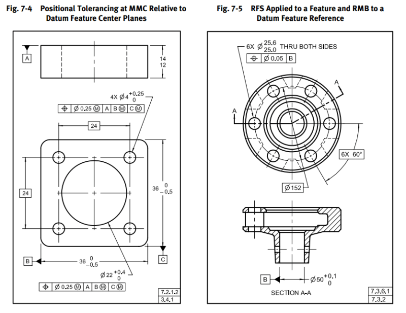
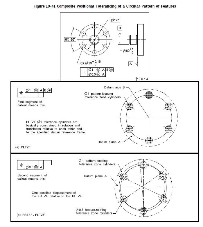
Web hole pattern located by composite tolerancing (primary and secondary datums in lower segment). That gives us the following true position formula: This is a.
Composite Position Tolerance for Hole pattern. Drafting Standards, GD
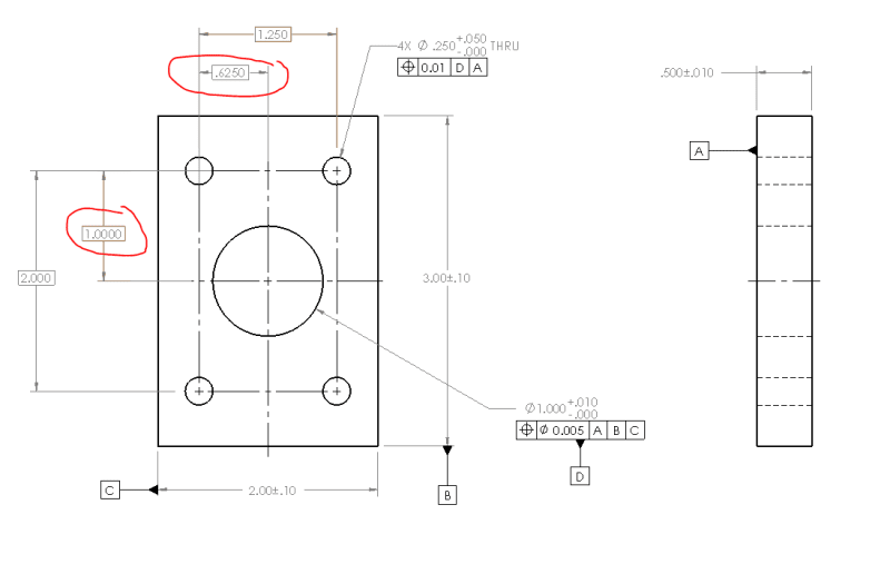
The #x designator is used to prevent redundant dimensions when a print has multiple identical features or a pattern. This figure represents one of the.
Hole Pattern Position With Central Hole as Datum Drafting Standards
It's really another virtual condition, but when it's applied to a datum feature of size all of the cool gd&t geeks call it a max.
Common GD&T Student Questions A Pattern of Holes as a Datum Feature
Let’s have a look at this simple plate with six holes in figure 1 and see how they are dimensioned. Web the position tolerance is.

Common GD&T Student Questions A Pattern of Holes as a Datum Feature
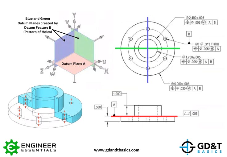
The max material boundary is the. Let’s say we’re off by 0.0015 in both x and y. Web the datum scheme simply does not reflect.
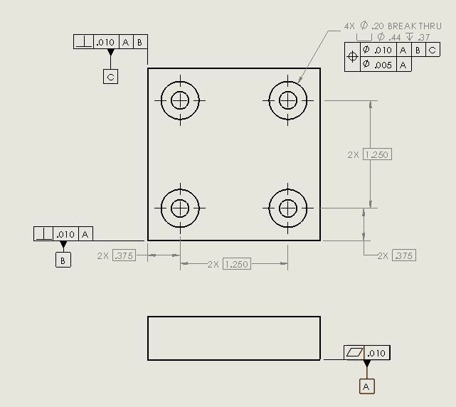
Web Composite Tolerances Are Used When We Have Relatively Looser Location Requirements But Tighter Orientation Tolerances.
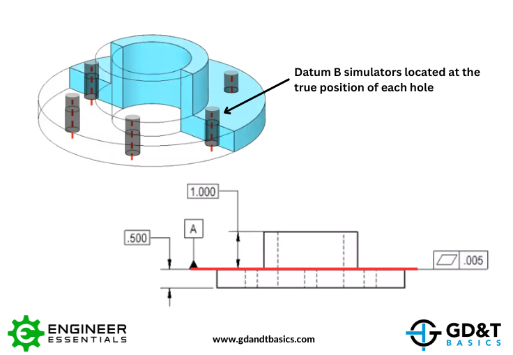
The large center hole is then located. True position = 2 x. All four locating holes are designated as pattern datum [b]. Web the intended interpretation of the gdt in detail c:
This Is A Typical Example Of What You May Find In A Number Of Companies.
Create an axis through one of the holes (never use an axis that's part of a feature unless you want to make things more difficult) and then choose in dimension or whatever is right for the version of ptc software you are using. (click on the image to enlarge.) image courtesy of. Tolerance stack is avoided by using gd&t feature controls. Web hole / feature pattern plot ;
As We Saw Earlier, Slots Allow Us To Avoid Overconstraint While Having Greater Precision.
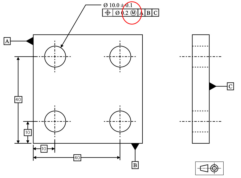
The number placed in front of the x represents the number of repetitive features that the dimension applies to. And most likely it does not reflect how the part will be inspected. Note that the yellow and blue circles represent the tolerance zones with 0.5 mm and 0.1 mm diameters, respectively. The holes in the pattern have a feature size tolerance of ±0.1 mm and a position tolerance of 0.5 mm at mmc with respect to datum reference frame abc.
G&T Geometric Tolerancing Iso 1101 Training ;
This can be polar (radius/angle) or cartesian (x,y coordinates) or. This designator is commonly used for holes, radii, chamfers, surfaces, and any other types of repetitive. The better datum scheme, the one that reflects how the part functions and how it should be gaged, is shown below. Let’s have a look at this simple plate with six holes in figure 1 and see how they are dimensioned.