Beam Pattern - Some headlamps have a small dot or circle at the center. Another commonly quoted beamwidth is the null to null beamwidth. The axis of maximum radiation, passing through the center of the main lobe, is called the beam axis or boresight axis. This is achieved by combining elements in an antenna array in such a way that signals at particular angles experience constructive interference while others experience destructive interference. Initial beam detection is employed during the cell detaction and rach process. All transducers should have a measured beam pattern, showing the magnitude of the main lobe and associated side lobes. From the figure, it can be noted that the beam pattern for scaled lcmv has a gain of 20 db below the beam pattern of the standard lcmv for. Efficiency accounts for the actual losses of a particular. P1,p2,p3 are being employed in connected mode. Web this article mainly describes the relevant elements of the beam pattern of led headlight bulbs.

Simulated beam patterns with predefined beam direction degrees. Three
Another commonly quoted beamwidth is the null to null beamwidth. In other words, there is only one degree of freedom for the beam pattern; Web.

Illustration of the beam patterns adopted in the first (a) and second
Examples found in their language folder. By reading this article, you can understand the factors that affect the beam pattern, know how to adjust the.

Broadside beam patterns normalized and shown in dB (H/E planes
The result is the sidelobe performance of the overall array degraded off boresight. Web in (3.4), the element patterns must be represented such that the.

Example of a simulated farfield beam pattern of an ultrasonic array
(eng) hashigo is a 4 colors knitted wrap mixing fingering and mohair. The developed framework relies only on receive power measurements and does not require.

Polarshaped beam pattern. Download Scientific Diagram
This framework adapts the beam pattern based on the surrounding environment and learns how to compensate for the hardware impairments. The elements are arranged in.

Illustration of the beam patterns adopted in the first (a) and second
Initial beam detection, p1, p2, p3. Compared with the multitask testing system used in reference , which can only complete a single scan of 7.
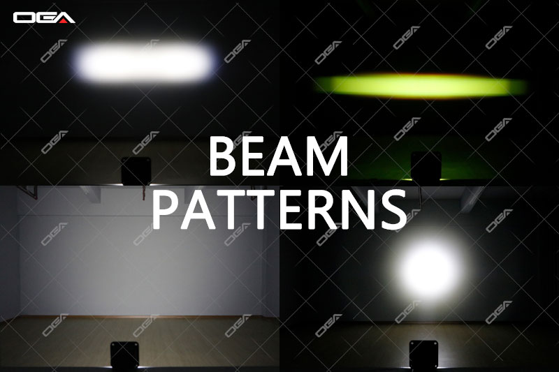
LED Beam Patterns Explained
Element factor and array factor combine to form the total antenna pattern. You can steer the beams by adjusting the phase of the signals to.
Beam Patterns AngryMoose Lighting
The single decorative beam in the center of this living room’s ceiling helps to carry the wood tones throughout the. Web parabolic antennas (such as.

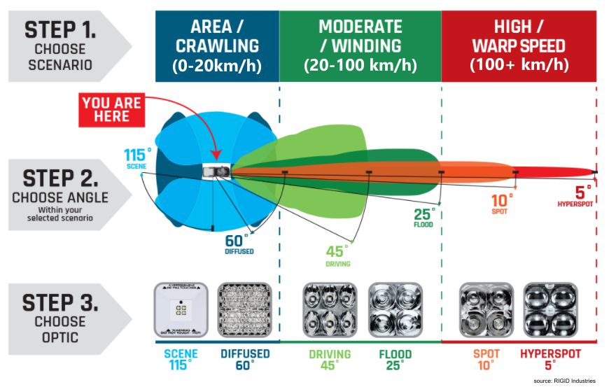
What is a good headlight beam pattern? (DOT/ECE)
You may want to think about what the symmetry would be for. Web parabolic antennas (such as those used in satellite television receivers) have a.

Normalized beam pattern obtained with a visible light source (Color
Web beamforming or spatial filtering is a signal processing technique used in sensor arrays for directional signal transmission or reception. Make a tape cross over.
Web Beamforming Or Spatial Filtering Is A Signal Processing Technique Used In Sensor Arrays For Directional Signal Transmission Or Reception.
Efficiency accounts for the actual losses of a particular. You may want to think about what the symmetry would be for. Initial beam detection is employed during the cell detaction and rach process. Element factor and array factor combine to form the total antenna pattern.
Web Parabolic Antennas (Such As Those Used In Satellite Television Receivers) Have A Typical Directive Gain (Or Simply Gain) Of 37.5 Db.
Are a classic pairing—and for good reason. Web this paper introduces a structured beam with archimedes spiral intensity distribution. Another commonly quoted beamwidth is the null to null beamwidth. We observed the spiral intensity patterns using computational holography, achieving the tuning over spiral arms number and spiral.
We Will Come Back To The Primary Elements, And The Beam Pattern, Or Primary Beam, Shortly.
By reading this article, you can understand the factors that affect the beam pattern, know how to adjust the headlight beam pattern from the inside and outside, and judge which situation you need to adjust the headlight beam pattern. All transducers should have a measured beam pattern, showing the magnitude of the main lobe and associated side lobes. In other words, there is only one degree of freedom for the beam pattern; 3.2 phase and time scanning beam forming and beam scanning are generally accomplished by phasing the feed to each element of an array so that signals received or transmitted from all elements will
The Main Beam Loses Amplitude At The Rate Of The Element Factor.
Antenna gain incorporates directivity as well as the efficiency of the antenna. From the figure, it can be noted that the beam pattern for scaled lcmv has a gain of 20 db below the beam pattern of the standard lcmv for. You can steer the beams by adjusting the phase of the signals to each element without physically moving. A referential point for all these types of radiation is the isotropic radiation.